A new bearing design is able to perform under high-thrust loads while still maintaining its excellent misalignment characteristics.
Today’s modern wind turbines can produce more than 7 MW of electrical power per unit — with offshore prototypes capable of achieving an output of as much as 12 MW — making these majestic machines an indispensable source of energy to help mitigate the detrimental effects of climate change. Consequently, ensuring that wind turbines operate reliably with minimal downtime is vitally important — not just for the environment, but also for wind-farm operators, utilities, and their customers. One area of opportunity for improving wind-turbine reliability involves the rotor shaft bearing support, a vital component inside the turbine’s nacelle where the bearing is subjected to particularly high loads.
In response to increasing incidents of failed bearings in the field, global industrial and automotive supplier Schaeffler began an investigation into the causes of these main bearing failures. In addition to generating significant improvements to currently used bearing solutions, Schaeffler’s research resulted in a new spherical roller bearing design for wind-turbine main shaft applications that offers high wear resistance as well as considerably lower friction torque and operating temperatures than the conventional standard. As such, this innovation has the potential to significantly extend the turbine’s operating life.
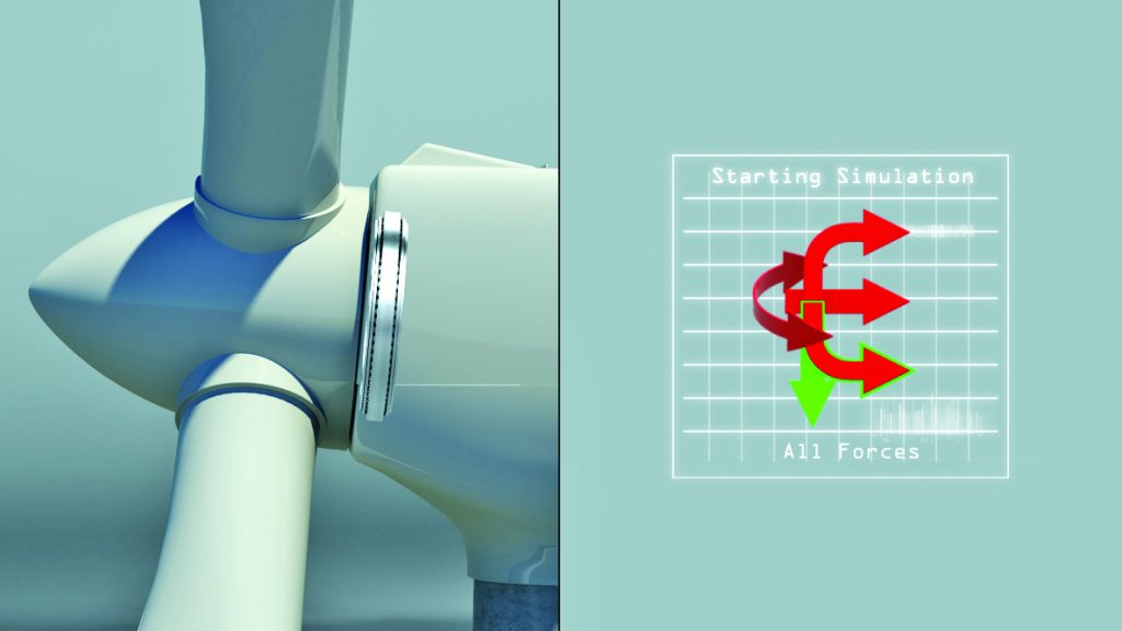
Figure 1: Rotor shaft bearings are subjected to a range of dynamic loads, especially high axial loads.
Recognizing an opportunity for improvement
Inside a wind turbine, the main shaft supports the main rotor hub and transmits rotational energy in the form of torque from the rotor hub to the gearbox. This application requires high reliability as well as robust resistance to the high loads generated by the rotor blades.
Due to the high levels of thrust generated in this environment (see Figure 1), conventional double-row symmetrical spherical roller mainshaft support bearings used in wind turbines experience uneven internal load distribution between the roller rows. This causes the rotor-side row to have lower load, while the gearbox-side row is potentially overloaded. Because of the low speed of the rotor shaft, only a minimal grease lubrication film is generated.
This, in turn, produces a metal-to-metal running condition. The result: a high rate of surface wear, poor performance, and, ultimately, premature bearing failure.
As part of Schaeffler’s extensive investigation of failed bearings — which was based on data obtained by analyzing the performance of approximately 10,000 wind turbines throughout the world — it was noted that a significant percentage of failures occurred mostly in bearings used in 3-point support rotor shaft systems. This shaft system is fitted with standard spherical roller bearings designs that feature two rows of symmetrical barrel rollers. Most of the damage was found to be concentrated internally on the axially loaded row (downwind) of the locating bearings. The damage, observed primarily at the surface level, is classified in accordance with ISO15243 as either fatigue occurring near the surface (also known as surface distress) or abrasive wear.
As mentioned earlier, abrasive wear in wind turbine main bearings operating under random conditions is primarily caused by varying shaft speed and loads that can lead to a very thin or nonexistent lubricating film. If the separating lubricant film between the roller and raceways surfaces is allowed to degrade, micropitting, smearing, and, eventually, extensive damage (spalling) at surface levels will be the result (see Figure 2).
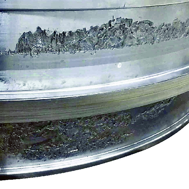
Figure 2: Spalling on the gearbox-side of a wind turbine main shaft bearing: the result of uneven load conditions.
Optimizing the existing standard
In order to offer customers a choice of solutions that would best meet their objectives and budget requirements, Schaeffler began by looking at optimizing the performance and service life of standard spherical roller bearings currently used in this application.
The first step was to develop and validate a lubricant formulated with the proper load-carrying properties for a variety of operating conditions, including low shaft speeds and extreme loads. Beyond merely improving the lubrication conditions, however, a strong emphasis was placed on optimizing the bearing design with enhancements such as extremely strict surface finish limits and special coatings on the rollers.
To that end, Schaeffler optimized the standard bearing design by applying the company’s proprietary Triondur® C coating to the rollers. Triondur C is a metal-containing hydrogenous amorphous carbon coating that offers a high level of protection against abrasive and adhesive wear (see Figure 3). Due to its highly ductile coating structure, Triondur C can withstand the high contact pressures that routinely occur in rolling bearing applications. As a result, rollers finished with Triondur C (see Figure 4) significantly reduce sliding friction and minimize sliding-induced damage. To further mitigate the potential for sliding, Schaeffler’s upgraded bearings use a two-piece brass cage that enables each roller row to rotate independently.
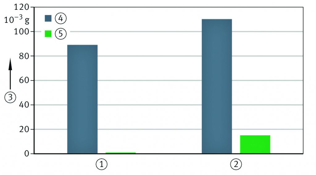
Figure 3: Comparing wear on uncoated vs. Triondur C-coated rolling elements.
Other enhancements to the standard spherical roller bearing design included:
1. Improving the quality of the internal components’ surface finish.
2. Optimizing the osculation (i.e. the roller-to-race conformity) in order to obtain the lowest contact pressures.
3. Using rollers with logarithmic profiling to reduce surface damage in the most critical contact areas.
4. Optimizing the internal clearance to both reduce the rotor shaft displacement under heavy thrust loads as well as improve the load-per-roller distribution.
5. Adding a central rib to the inner ring in order to increase axial rigidity as well as improve contact pressure distribution throughout all rollers to reduce surface damage.
In addition to optimizing the bearing itself, Schaeffler also looked at how the bearing replacement process could be made more efficient and economical. This analysis included considering the shaft on which the bearing is mounted. Due to the heavy fretting corrosion and material attrition that occurs during normal operation, many of these shafts require a reworked mounting surface — a complex and expensive process that involves removing the damaged layer and replating the shaft’s outer diameter to return it to its original dimension. Not surprisingly, having to rework a shaft typically adds to the wind turbine’s downtime. Schaeffler’s solution: Save money and time by using a bearing with an undersized bore, thereby eliminating the need to rebuild the shaft altogether.
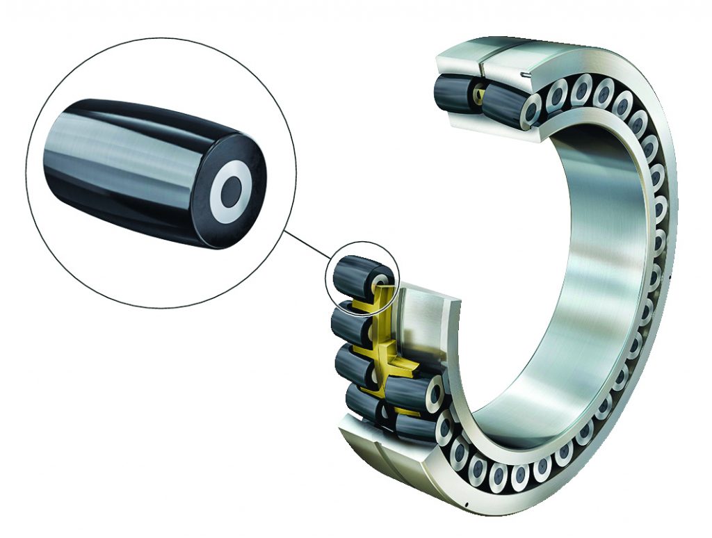
Figure 4: Bearing rolling element with Triondur C coating.
Engineering a design breakthrough
Beyond merely optimizing the conventional bearing design used in most wind turbines, however, Schaeffler was determined to provide the ultimate bearing solution that would be able to perform under high-thrust loads while still maintaining its excellent misalignment characteristics. To that end, Schaeffler developed and patented a new bearing design for main shaft bearings in wind turbines: the asymmetric spherical roller bearing. The term “asymmetric” refers to the bearing’s different contact angles, which serve to improve the load distribution between both bearing rows, reduce the contact pressure and friction torque, and increase axial stiffness by approximately 50 percent. Moreover, the bearing’s unique design prevents roller-to-raceway contact stress peaks from developing as a result of the periodic bending of the rotor shaft during operation or accuracy errors that arise from the initial assembly inside the wind turbine’s nacelle.
The operating principle behind Schaeffler’s asymmetric spherical roller bearing is as follows: While the rotor side of the bearing is designed to carry the normal radial load present in the application, the gearbox side of the bearing is optimized with an increased contact angle to accommodate the high thrust. During operation, the potentially damaging thrust is safely transferred through the bearing and transmitted to the housing support (see Figure 5). The innovative asymmetric design ensures a more even internal load distribution, which provides improved rolling motion while minimizing sliding. The result: less torque, less friction, and less heat. Plus, the axial displacement of the bearing is also reduced. Bottom line: The overall efficiency of the system is improved, which allows the wind turbine to generate more power.
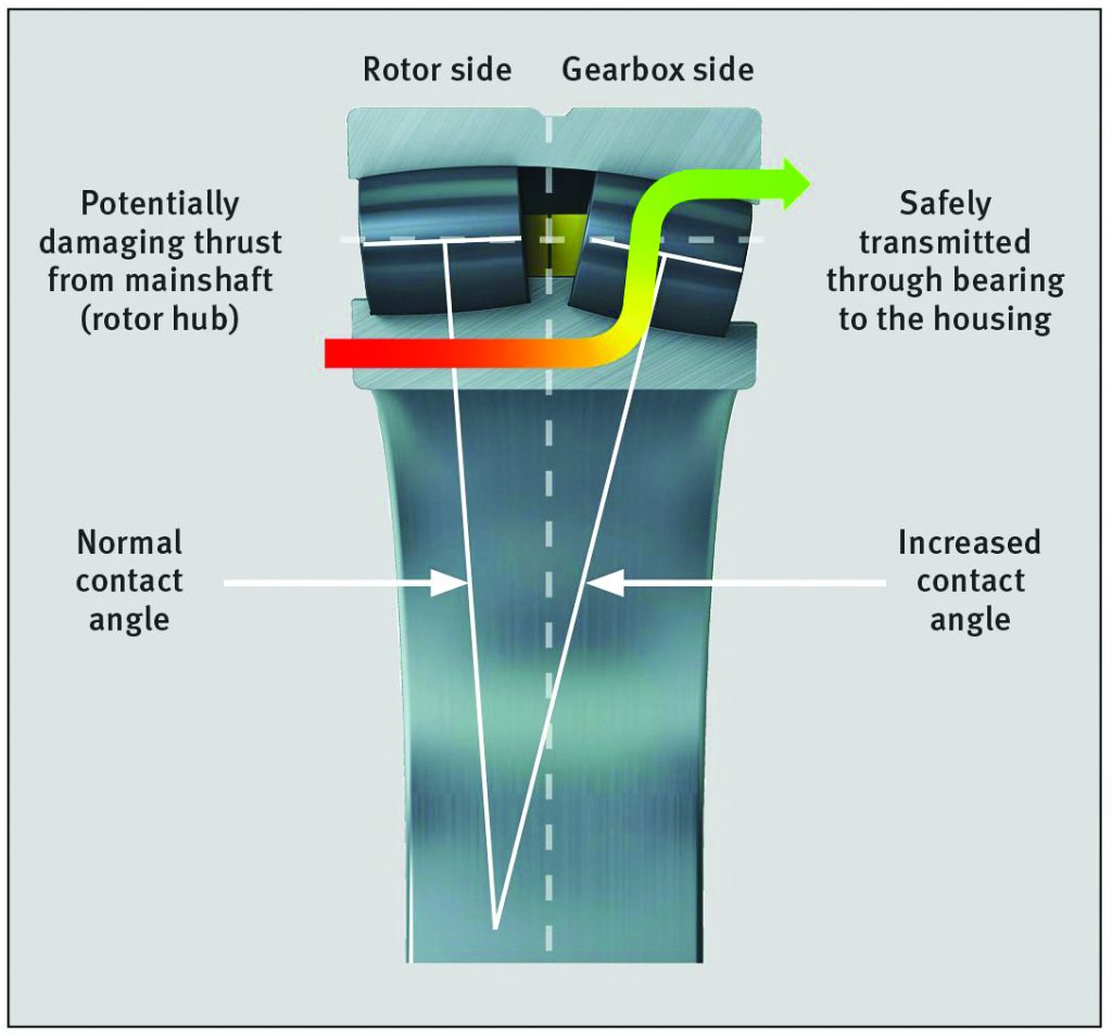
Figure 5: Cross section of asymmetric spherical roller bearing showing load being transferred through bearing.
Validating the benefits through rigorous testing
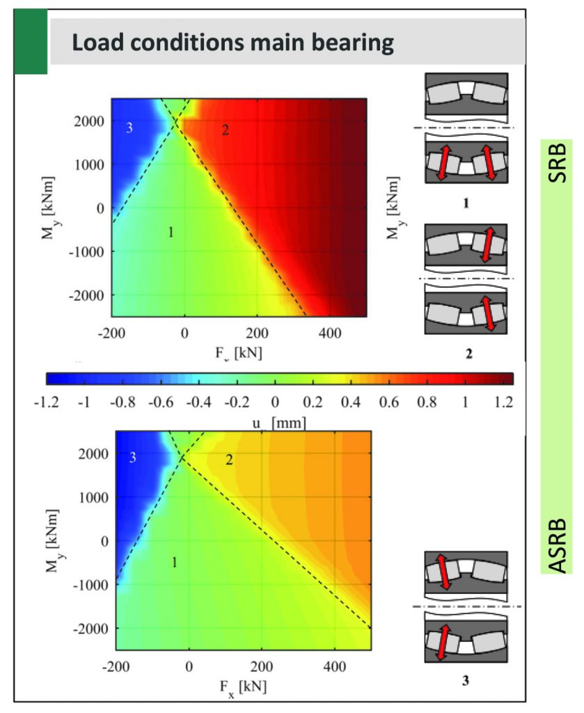
To validate these claimed performance improvements, a comparison test was performed at Germany’s University of Aachen in which a standard, commonly used 240/710-size spherical roller bearing was pitted against Schaeffler’s new asymmetric design. The bearings were tested by simulating real-life conditions inside a test rig fitted with 232 sensors placed in strategic locations throughout the nacelle to monitor all operating conditions such as main bearing loads, acceleration, and deflections as well as potential adverse impacts of excessive axial displacements.
The test results revealed that Schaeffler’s asymmetric design provides better load distribution between both roller rows under a combination of axial and moment loads. In Figure 6, the region in the graph marked “1,” which represents loads distributed between both roller rows, is considerably larger for the asymmetric design (bottom graph) than for its conventional counterpart (top graph). Similarly, a standard spherical roller bearing exhibits considerably more axial displacement as shown by the top graph’s darker red color in the region marked “2,” which represents the loads applied only to the downwind roller row.
Contact: Enya Chen
Phone: +86 15965629650
E-mail: leadbearingca852@gmail.com
Whatsapp:+86 15965629650
Add: No. 30 Jiwei Road, Huaiyin, Jinan, China
We chat
